Home › Forums › Explore Media › Printmaking › Building an etching press
- This topic has 29 replies, 1 voice, and was last updated 1 year, 1 month ago by
 Marie.
-
AuthorPosts
-
March 16, 2006 at 12:30 am #985633
I’m a little uncomfortable right now as this is my first post here, but another user has encouraged me.
I am a long-time (part time) fine art photographer — photographing and working in the darkroom for more than 40 years — but I have turned to printmaking in the last year.
I have never had a lot of money, so I have built almost all my own equipment — including my own cameras and darkroom equipment.
I could not even begin to afford purchase of an etching press, so I decided to build one from scratch. I have developed reasonable machining skills from having built the cameras, etc., so I designed and built the thing from complete scratch (with my own two hands – no outside labor or services involved) from “scrap” raw materials which I collected slowly over a half a year.
The bed of the finished press is 24″ wide, and it is 34″ long overall. It is made (mostly) of 3/4″ aircraft aluminum (6061), though some parts are heavier.
The platen is fully supported by steel rods and plastic bearings for the full length of the bed.
I made the rollers using a somewhat unique design, at least for what I observed in my study of existing designs. They are a composite assembly of steel and aluminum. They were considerably more difficult to make than solid rollers, or hollow rollers with welded ends, would have been. But I did do some analysis of what I thought the stress loads problems would be; I believe the finished rollers are stronger than equivalent-sized solid steel, but weigh about 1/3 as much.
The upper roller is 3.5″ diameter; the lower is 2.9″ diameter. I turned them on my lathe so they are concentric and smooth within 0.001″ over their entire size.
Weight (or lack of same) does seem to be the biggest problem with the press — it only weighs about 150-ish lbs. I made a “crank” drive instead of a “wheel”, so there is a fair amount of “vertical” force in the direction of lifting the press for 1/2 the turn. I need to make brackets to bolt the press down to the cart I made.
The press has a 1::2.8 chain drive made from ANSI #40 chain and solid steel sprockets. That has a breaking strength over 8000 lbs — strong enough for sure!
The upper roller “tensioners” are driven by 1/2-20 steel threaded rods. Then,even with relatively crude paper scales to gauge the top roller’s height, the actual height of the top roller can be easily determined within about 0.005″, because the screws lift or lower the roller 0.050″ in one complete turn. Hence, no micrometers are needed to achieve ablout 0.005″ repeatability.
I have also made a UV light box suiltable for up to 16×20 prints, though I only have a 14″x17″ (home made, naturally) printing frame.
I have also been doing a lot of research into digital negatives (well, digital positives), starting with the techniques in Mark Nelson’s “Precision Digital Negatives”.
For what it’s worth!
– Don
March 16, 2006 at 4:00 am #1068541do post pictures… we love pictures!
and I for one am interested in your design for the rollers!March 16, 2006 at 6:34 am #1068535Don… Welcome to the Printmaking Forum… and don’t feel uncomfortable. We are a very warm, friendly bunch that is very curious about what other printmakers are doing…
So I’m glad you made it over here… I know Andrew (Printmakerguy) will be along shortly with smarter questions than I have (since he’s building his own press at the moment).
My question: how difficult is it to run the bed through, given the gear ratio?
Diane
March 16, 2006 at 7:03 am #1068545I am interested in your design as well! What did it cost you to build?
March 16, 2006 at 8:56 am #1068537I am glad you posted- We don’t bite

You’ll have to show off some pictures!!
I spent a fair amount of my day yesterday machining parts for my press as well…. Mine is also mostly 6061 aluminum, with the exception of the rollers, which are steel- and SHOULD be finished either tonight or tomorrow. I had someone else make those, as I don’t have the facilities to deal with that big of a piece (they are 24″ x 8 1/4″).
You can check out my press project so far on this thread!
Hope to see some pics of yours soon…
-Andrew
[FONT="Arial"]
I always welcome critiques and criticisms of my work! That's the only way to improve!My My Web Page - My Miniature Work-http://www.lessthansix.com[/center]
-Member of the Association Of Miniature Artists-
* AMA * MASF * HS * ARMS *March 16, 2006 at 12:28 pm #1068546Here is a rough diagram of the construction of my rollers. Note: this drawing is NOT to scale at all — it is only conceptual.
The basic mechanical concept is called a “box beam”, which is commonly used in bridge and industrial construction. A box beam’s strength (especially bending strength) can exceed that of a solid piece of the same size made of the same materials.
This sketch is a “cutaway side view”; you’re looking at the roller as if it had been cut in half lengthwise:
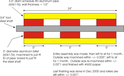
How is it held together? I machined “weldon flats” on the steel shaft.
The cylindrical aluminum billets connect using 3/8-16 x 3/4″ alloy set screws
(3 per sub-cylinder) set in with loctite. The outer cylinder was drilled and
countersunk for 1/4-20 stainless bolts; 9 per roller set in cylindrical symmetry.Once the bolts were installed, the countersunk areas
were filletted with steel filled epoxy resin and machined along with the rest
of the assembly.Note: To build this kind of thing, you need a lathe which is more than
about 30″ center-to-center; that is not the usual kind of “Harbor Freight”,
etc., “mini lathe”. My lathe is 12×36, which is (just comfortably) large enough to have done this job.March 16, 2006 at 2:10 pm #1068538Pretty impressive.
I don’t have a lathe myself, only a mill- So I can’t turn anything, I had a local shop do that for me. I used Steel pipe on mine, and a 1 1/4″ steel center shaft.
You are working to some pretty tight tolerances there- I am impressed
 This thing could be a space shuttle part. Mine is a little more crude (far more crude, really). I am not a machinist. I get it close, but there is a lot of room for ‘play’ with these presses…
 -Andrew
[FONT="Arial"]
I always welcome critiques and criticisms of my work! That's the only way to improve!My My Web Page - My Miniature Work-http://www.lessthansix.com[/center]
-Member of the Association Of Miniature Artists-
* AMA * MASF * HS * ARMS *March 16, 2006 at 4:24 pm #1068547Andrew,
Thanks for your nice words!
A mill is absolutely indispensible, but the lathe is, also. Besides, it did my heart a huge amount of good to have the rollers set up between centers, turning at 1500 rpm without even a slight trace of vibration!
You brought up a very interesting point, which I have also surmised in the year or so this project has taken. Most of the commercial manufacturers seem to be trying to sell presses as if they must be as strong as the Queen Mary, half as heavy as the Empire State Building, and machined to the tolerances of a fine Swiss watch.
On the other hand: I did read a piece by someone who did some level of successful intaglio using the mangle from an old washing machine. And if you look at http://www.waterbasedinks.com, you’ll see that they sell a rolling-pin looking device for “making prints on the road”.
Moreover, I actually tried to work out some of the real stresses on the machine, and they just are not that high. Maybe they are very high in the minds of laymen (well, you’re quoting thousands of pounds per square inch, after all), but not that high for people who ordinarily work with machinery.
I can’t resist to reduce the “pressure” argument to some level of absurdity: I’m sure that most people remember vinyl LP records, yes (even if they never handled one)? The styli for those records were typically elliptical diamonds with a major axis of about 0.003″, and a minor axis of about 0.0015″. Even if you had a fairly “light” pressure of the tonearm on the record — something like 2 grams — **the net force exerted by the stylus on the side of the groove was on the order of tonnes per square cm**. On vinyl!
Also, it has become very difficult for me to convince myself that I needed 0.001″ parallelism between the rollers, given that I would be pulling a print with ~3/8″ of felt between the upper roller and the print, and 1/2″ of steel or phenolic between the lower roller and the print.
My gut, as I’m approaching the end of the (demanding) manufacturing project, is that I’m very happy — from a personal satisfaction point of view — that I achieved good accuracy in the construction, but that the accuracy I achieved is far, far, greater than the machine actually requires.
I think that I am going to have to take some digital pix of the finished beast and post them here…
Cheers,
– Don
March 16, 2006 at 4:46 pm #1068539When it comes to press tollerences, I remind myself that people have been pulling etchings for hundreds of years. Did rembrant’s press (or his printers, more correctly) have rollers that were EXACT to a hundredth of an inch? I doubt it. Would it matter? Like you mention, you are going to have felts, and a phenolic (or even plywood in some cases) bed that you are printing on… So a little imperfection here and there is not going to matter.
Also, as you point out, the numbers seem really high- But that pressure is on a very, very small portion of the roller… I suspect that most, if not all, commercially availible presses are WAY overbuilt.
Take Doug Forsythe’s plans, for instance- Which I based my press on. The plans call for 1/2″ steel side rails… This thing could take a round from an antitank weapon with minimal damage- Great for those who work in a war zone, but a bit of overkill for those who don’t….
While your accuracy is probably far more than you needed, I am a firm beleiver in having tools that are as beautiful as the work that they produce… So why not go that extra step??
-Andrew
[FONT="Arial"]
I always welcome critiques and criticisms of my work! That's the only way to improve!My My Web Page - My Miniature Work-http://www.lessthansix.com[/center]
-Member of the Association Of Miniature Artists-
* AMA * MASF * HS * ARMS *March 17, 2006 at 4:11 am #1068542Thanks for the picture of the roller! Happy to see that works actually…
I had dreamed up the same design, but I lack the mechanical skills, time and the machines to make those.
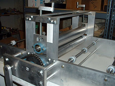
How is the roller suspended?March 17, 2006 at 5:59 pm #1068548I took some digital pictures of my new “beast”, for those who asked (I think it needs a name. I don’t really have a name for him / her / it.)
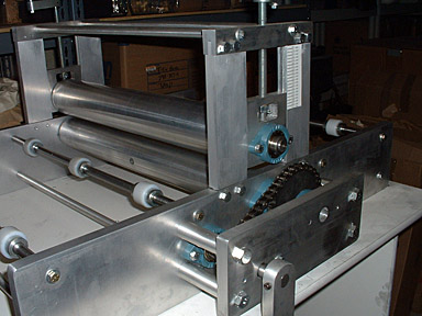
For size comparison scale: the aluminum side plates are 3/4″ (18mm) thick, and are 6″ (150mm) high. The bed length is 34″ (87 cm), and the “inside” bed width is 24″ (61 cm).
There are some resemblences to Doug Forsythe’s press here, but some important differences:
1) The rollers are of the compound construction I described earlier in this thread.
2) Note that the supports for the upper roller are machined into the sides of the press. That is, I cut “mortises” and “tenons”. This was a lot of extra work. However, it means that (a) the claimed width of the bed is indeed the width of the bed, and (b) no “stops” were required. The platen rides about 0.275″ below the top level of the sides; that 0.275″ is plenty to keep the platen where it belongs!
– Don
————————————-
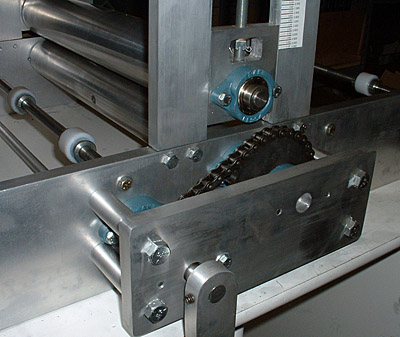
Chain drive “outrigger” and bearings. Note that the position for the lower roller and the geometry of the “outrigger” were built so that the sprockets (and drive gear ratio) could later be changed, after experimentation, without changing anything in the construction of the machine. Those bolts holding the “outrigger” are grade 5 1/2-13, and they run through aluminum cylinders 1″ in diameter which were bored. They are not “going anywhere”, so to speak!
The bearings are in compensating cast iron mountings.
That crank (you can only see the top) is also cut from 3/4″ aluminum, and
has a rotating steel handle at the other end.
Overall. Note I designed things such that there are essentially no “nuts” used in the construction (to get lost later). All the lengths of screws and bolts are calibrated to “come out even”, so there are no protrusions of bolt ends anywhere.
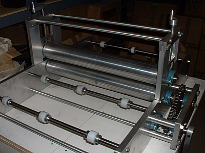
From the right side
Mountings of rollers, gears, “superstructure”. The castellated nuts in the upper roller mountings are bushed, so it is just as smooth to raise the upper roller as it is to lower it. The range of motion of the upper roller is over 3″. The upper “spreaders” are 5/8″ tool steel, mounted with grade 8 bolts. The lower “spreaders” are 5/8″ 5051 aluminum rod. The “bearings” for the platen are machined UMHW (“ultra high molecular weight polyethylene”, sort of similar to delrin in behavior. They are positioned with shaft collars.
 March 17, 2006 at 6:02 pm #1068536March 17, 2006 at 6:25 pm #1068549
Diane,
Thanks for the nice reaction!!
It IS pretty big, indeed. I had to build the cart it is sitting on “just for the occasion”, as nothing easily / commercially available was available (to say nothing of “at a reasonable price”). The top of the cart is 36″ x 26″!
Nearly a year ago, when I first obtained the material for those side panels, the package was so large and heavy that I was certain I had lost my mind …
By the way: someone asked in this thread “how much did it cost to build?”. If I really give an answer, the answer is misleading, because I did 100% of the labor. To do that, one requires a milling machine, a good sized lathe, a floor-mounted drill press, and a metal-cutting bandsaw at least. Without those tools, you will necessarily have work done “outside”.
All that said, my direct cost of materials-only has been something like $500.
If one would need to purchase outside machining services, I would guesstimate a minimum of an additional $750 to $1000. This depends very much on where you are; the price of machinists varies quite a lot depending on “supply and demand”. Andrew could answer this question better than I, as he is in the middle of the process.
This guesstimate would make sense in terms of list prices for similar “production” machines, which would be in the $3000+ range, I suspect. That makes their “cost” in the area of, perhaps, $1200-ish.
– Don
March 17, 2006 at 6:30 pm #1068550Oh, and, Diane —
I believe you just sexed the press for me. The press is, henceforth, a “she”.
– Don
March 17, 2006 at 6:52 pm #1068540Great looking machine…
Similar production machines for $3k? Not really… Try 4-5K at LEAST!
And, I doubt that they are that well built
-Andrew
[FONT="Arial"]
I always welcome critiques and criticisms of my work! That's the only way to improve!My My Web Page - My Miniature Work-http://www.lessthansix.com[/center]
-Member of the Association Of Miniature Artists-
* AMA * MASF * HS * ARMS * -
AuthorPosts
- You must be logged in to reply to this topic.
Register For This Site
A password will be e-mailed to you.
Search